19.2 Solution
The lattice paths is actually a problem from the field of combinatorics. In our particular case (3x3 grid) it could be solved (number of paths calculation) with a Pascal’s triangle (covered in Section 18) or the build-in binomial function (binomial(nRows+nCols, nRows)). Since I’m not a mathematician, then for a detailed explanation I refer you to this Wikipedia’s entry.
Still, for practical reasons I like to use computer calculations to help me with my understanding. Let’s start small. First, analyze the pictures in Figure 9 and Figure 10.
Note: The solution presented here is practical only for small girds (up to 4x4 lattice, 70 paths to calculate and to draw). The original problem (20x20 grid) got
binomial(40, 20)= 137846528820 possible routes between the top-left and bottom-right corner. That’s far too many to calculate with the presented method and to draw in one figure.
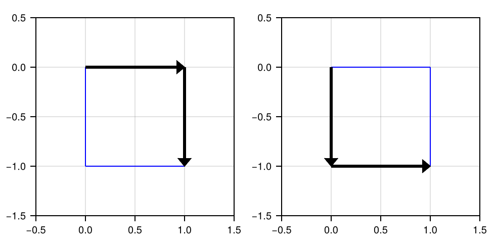
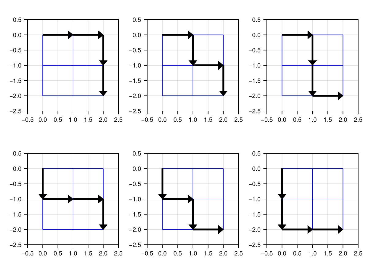
A few points of notice (make sure they agree on both Figure 9 and Figure 10):
- the top left corner could be considered to be the center of our Cartesian coordinate system with the location (0, 0);
- the bottom right corner could be located within that system at the position (nRows, -nRows) or (nCols, -nCols) of our grid (each small square in Figure 9 and Figure 10 got the side length = 1 and builds rows and columns of a large square);
- The number of arrows used to reach the destination (the bottom right corner) is always the same for each path and it is equal to nRows+nCols (or nRows*2 or nCols*2);
Equipped with this knowledge, we can finally do something useful.
const Pos = Tuple{Int, Int}
const Mov = Tuple{Int, Int}

const RIGHT = (1, 0)
const DOWN = (0, -1)
const MOVES = [RIGHT, DOWN]
const STARTPOINT = (0, 0)

function add(position::Pos, move::Mov)::Pos
    return position .+ move
end

function add(positions::Vec{Pos}, moves::Vec{Mov}=MOVES)::Vec{Pos}
    @assert !isempty(positions) "positions cannot be empty"
    @assert !isempty(moves) "moves cannot be empty"
    result::Vec{Pos} = []
    for p in positions, m in moves
        push!(result, add(p, m))
    end
    return result
end
We begin by defining a few constants. The type synonyms: Pos (shortcut for position), Mov (shortcut for move) will save us some typing later on. Whereas, RIGHT (shift by 1 unit along X-axis) and DOWN (shift by 1 unit along Y-axis) are the arrow coordinates in the Cartesian coordinate system (it starts at the top left corner, (0, 0), of a big square), which together form a vector of available MOVES.
Next, we define the add function. Its first version, aka method, allows to add a position (like our STARTPOINT) to a move (like the move to the RIGHT). In some programming languages we would have to type something like return (position[1] + move[1], position[2] + move[2]) but in Julia we just use a broadcasting operator .+ to add the tuples element-wise. The second version of add takes a vector of any starting positions and any possible moves and adds each move to each starting position (using simplified nested for loop syntax we met in Section 2.2) to get the new positions (places on the grid) after the moves.
Let’s put the above functions to good use.
function getFinalPositions(nRows::Int)::Vec{Pos}
    @assert 0 < nRows < 5 "nRows must be in the range [1-4]"
    finalPositions::Vec{Pos} = [STARTPOINT] # top left corner
    for _ in 1:(nRows*2) # *2 - because of columns
        finalPositions = add(finalPositions, MOVES)
    end
    return finalPositions
end

function getNumOfPaths(nRows::Int)::Int
    @assert 0 < nRows < 5 "nRows must be in the range [1-4]"
    target::Pos = (nRows, -nRows) # bottom right corner
    positions::Vec{Pos} = getFinalPositions(nRows)
    return filter(pos -> pos == target, positions) |> length
end

getNumOfPaths(3) # the same result as: binomial(6, 3)20getFinalPositions accepts nRows which is the number of small squares in a column of, e.g. Figure 10. Next, it starts at the top left corner (finalPositions::Vec{Pos} = [STARTPOINT]) and moves away from it. The number of moves is equal to nRows*2 and we always go in each of both the directions (RIGHT and DOWN which are in moves) thanks to the previously defined add function. Finally, we return the finalPositions that we get after we made all the possible moves. Next, in getNumOfPaths, we choose only those positions that land us in the bottom right corner (target) by using filter. The length of our vector is the number of paths we were looking for.
OK, now let’s think how to draw it. For once, we could reuse the already written functions (add and getFinalPositions) like so (we will modify the functions a little bit):
function makeOneStep(prevPaths::Vec{Path}, moves::Vec{Mov}=MOVES)::Vec{Path}
    @assert !isempty(prevPaths) "prevPaths cannot be empty"
    @assert !isempty(moves) "moves cannot be empty"
    result::Vec{Path} = []
    for path in prevPaths, move in moves
        push!(result, [path..., add(path[end], move)])
    end
    return result
end

function getPaths(nRows::Int)::Vec{Path}
    @assert 0 < nRows < 5 "nRows must be in the range [1-4]"
    target::Pos = (nRows, -nRows) # bottom right corner
    result::Vec{Path} = [[STARTPOINT]] # top left corner
    for _ in 1:(nRows*2) # *2 - because of columns
        result = makeOneStep(result, MOVES)
    end
    return filter(path -> path[end] == target, result)
end
We begin with makeOneStep (analogue to add(positions, moves)), a function that makes every possible step (moves) from the last known location of every path in prevPaths. BTW, notice how defining the type synonyms paid off. Without them Vec{Mov} would be Vector{Tuple{Int, Int}} (it isn’t all that bad), but Vec{Path} would grow to Vector{Vector{Tuple{Int, Int}}}, which is a little monster. Anyway, thanks to the double for loop we add every possible move (here RIGHT or DOWN) to the last know location of a path (path[end], which is a Pos) and append it (push!) to the result (path... copies the previous vector, so [path..., add(path[end], move)] yields the previous path with a position after that move, e.g. [(0, 0)] becomes [(0, 0), (1, 0)]).
Once we know how to makeOneStep (remember we test both directions/moves at once, so we branch our paths into two separate paths at each step we take) time to take nRows*2 steps (with for) so that we can see which ones will eventually create the paths that will lead us to our final position (path[end] == target). As you have guessed this is exactly what getPaths does.
Let’s see how we did so far (simple minimal test, locate the points depicted with tuples on Figure 9).
getPaths(1) [(0, 0), (1, 0), (1, -1)]
[(0, 0), (0, -1), (1, -1)]I don’t know about you, but I’m pretty satisfied with the result.
OK, once we got the path, i.e. the stop points between which we draw the lines, making a Figure that depicts them should be a breeze. This could be done with, e.g. CairoMakie’s arrows2d function. However, there’s a small problem here, one look at the documentation and we see that the function requires two arguments, namely points (start points) and directions (like RIGHT and DOWN) and not a path which is starting point, pit stop, pit stop, […], end point. No biggie, we can get the directions in no time.
function getDirection(p1::Pos, p2::Pos)::Mov
    return p2 .- p1
end

function getDirections(path::Path)::Vec{Mov}
    directions::Vec{Mov} = []
    for i in eachindex(path)[2:end]
        push!(directions, getDirection(path[i-1], path[i]))
    end
    return directions
end
To getDirection we just subtract the position of a previous point on the line (p1) from the position of a next point on it (p2). By extension, in order to getDirections we do that for all the points. The last function’s body (getDirections) could be also replaced with the following one liner: return map(getDirection, path[1:end-1], path[2:end]) (similar to what we did in Section 2.2). Feel free to choose the version whose meaning is clearer to you.
Finally, time to draw.
import CairoMakie as Cmk

function addGrid!(ax::Cmk.Axis,
                  xmin::Int=0, xmax::Int=2,
                  ymin::Int=-2, ymax::Int=0)::Nothing
    @assert xmin < xmax "xmin must be < xmax"
    @assert ymin < ymax "ymin must be < ymax"
    for yCut in ymin:ymax
        Cmk.lines!(ax, [xmin, xmax], [yCut, yCut], color=:blue, linewidth=1)
    end
    for xCut in xmin:xmax
        Cmk.lines!(ax, [xCut, xCut], [ymin, ymax], color=:blue, linewidth=1)
    end
    return nothing
end

function drawPaths(paths::Vec{Path}, nCols::Int)::Cmk.Figure
    @assert length(paths) % nCols == 0 "length(paths) % nCols is not 0"
    r::Int, c::Int = 1, 1 # r - row, c - column of subFig on Figure
    sp::Flt = 0.5 # extra space on X/Y axis for better look
    xmin::Int, xmax::Int = paths[1][1][1], paths[1][end][1]
    ymax::Int, ymin::Int = paths[1][1][2], paths[1][end][2]
    fig::Cmk.Figure = Cmk.Figure()
    for path in paths
        ax = Cmk.Axis(fig[r, c],
                      limits=(xmin-sp, xmax+sp, ymin-sp, ymax+sp),
                      aspect=1, xticklabelsize=10, yticklabelsize=10)
        Cmk.hidespines!(ax)
        Cmk.hidedecorations!(ax)
        directions::Vec{Mov} = getDirections(path)
        points::Vec{Pos} = path[1:end-1]
        addGrid!(ax, xmin, xmax, ymin, ymax)
        Cmk.arrows2d!(ax, points, directions)
        if c == nCols
            r += 1
            c = 1
        else
            c += 1
        end
    end
    Cmk.rowgap!(fig.layout, Cmk.Fixed(1))
    Cmk.colgap!(fig.layout, Cmk.Fixed(1))
    return fig
end
We begin with a helper function addGrid! that does what it promises (draws blue lines in sub-figures of our main figure, see Figure 10). Then we move to drawPaths that draws each path of paths (for path in paths) on a separate sub-figure (its location is specified by fig[r, c]). A path is depicted with a set of arrows (arrows2d!) on the blue grid (addGrid!). We hid the Cartesian coordinate system (Cmk.hidespines! and Cmk.hidedecorations!) because in the end we don’t care about it that much. Moreover, we narrowed the empty space between the sub-figures (Cmk.rowgap! and Cmk.colgap!). The rest of the code in this snippet is just the necessary, housekeeping that helps us achieve our goal, which is depicted below.
paths = getPaths(3)
drawPaths(paths, 5)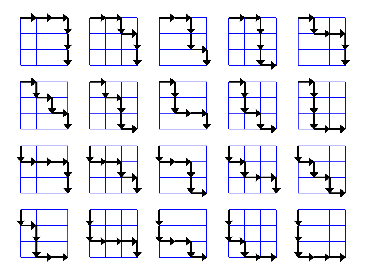
All is revealed. Behold the twenty paths on a 3x3 grid.